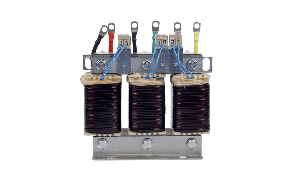
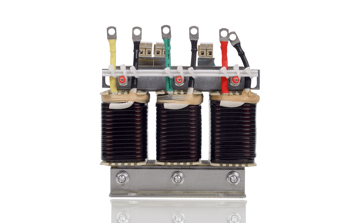
Overview
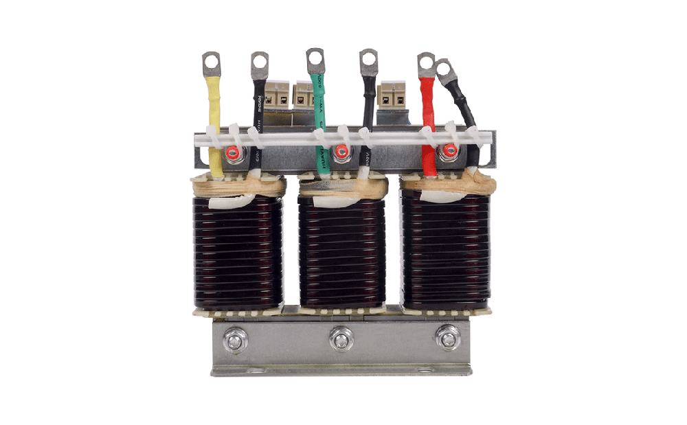
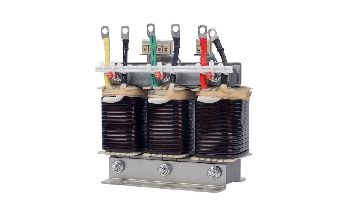
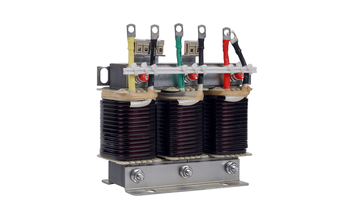
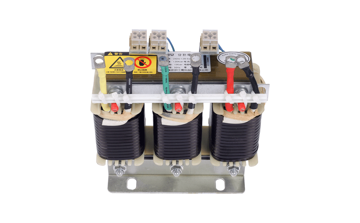
When compensating capacitive reactive power, the capacitor is often affected by the harmonic current, closing inrush current and operating overvoltage, resulting in capacitor damage and power factor reduction. Therefore, the series reactor needs to be installed in series at the front end of the capacitor to suppress and absorb harmonic waves to protect the capacitor so as to avoid the influence of harmonic voltage and current as well as impulse voltage and current, improve the power quality, improve the system’s power factor, prolong the capacitor life, and ensure the safe operation of the power grid.
Operating Conditions
1. The altitude shall not exceed 2,000 meters.
2. The operating ambient temperature shall be -25–45°C, and the relative humidity shall not exceed 90.
3. There is no harmful gas around and no flammable and explosive materials.
4. The surrounding environment shall have good ventilation conditions. If the product is installed in the cabinet, the ventilation equipment shall be installed.
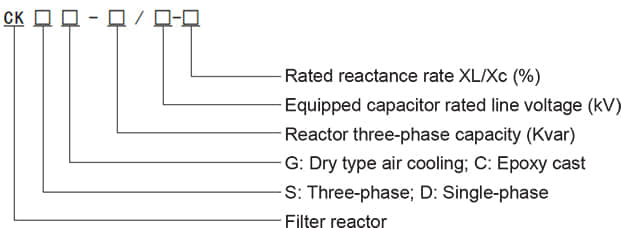
Model Description
Main Technical Parameters
1、Available capacitor voltages: 0.4 kV, 0.45 kV, 0.48 kV, 0.525 kV, 0.66 kV and 0.69 kV.
2、 Reactance rates: 1%, 4.5%%, 5%, 5.67%, 6%, 7%, 12%, 13.8% and 14%.
3、With the dielectric strength level of 5 kV/min, the insulation classes of Class B, Class F and Class H, the noise ≤ 30 dB and the overload capacity ≤ 1.35 times, continuous work is done.
4、 After installing the series reactor, the system voltage will rise. The calculation formula: UgUg=(n/n² -1)XUn(Capacitor bank working voltage: Ug; System rated working voltage: Un; Reactor tuning times: n)
5、The conversion formula among the reactor capacity, capacitance capacity, reactance rate and inductance value: UL = Uc phase XL/Xc L=UL/1X0.314(Capacitor capacity: Qc; Reactor capacity: Qw; Reactor terminal voltage: UL)Inductance value: L; Reactor current: I; Capacitor phase voltage: Uc phase: Uc phase Qw=Qc phase X XL/Xc Reactance rate=XL/Xc


